v5 of Custom Wireless LED Bands PCB
2024 Personal Project Embedded PCB Design
This one has it all: BMI160 IMU! Power Path! LED Strip Attachment! ESP32C3! And of course, USB-C.
Project Summary
This is version 5 of the Custom PCBs for my wireless synchronized LED accessory set. Though in fairness, this is actually the ninth PCB iteration manufactured for this project.
Motivation
Between v1 and v5 were many iterations that didn’t see a full-batch production (i.e. were assembled many times into a full set of operational bands), whether that was due to the PCBs simply not operating correctly or not meeting my personal standards. Along the way, I made many decisions on what the next full set would look like. This post focuses mostly on the PCB design.

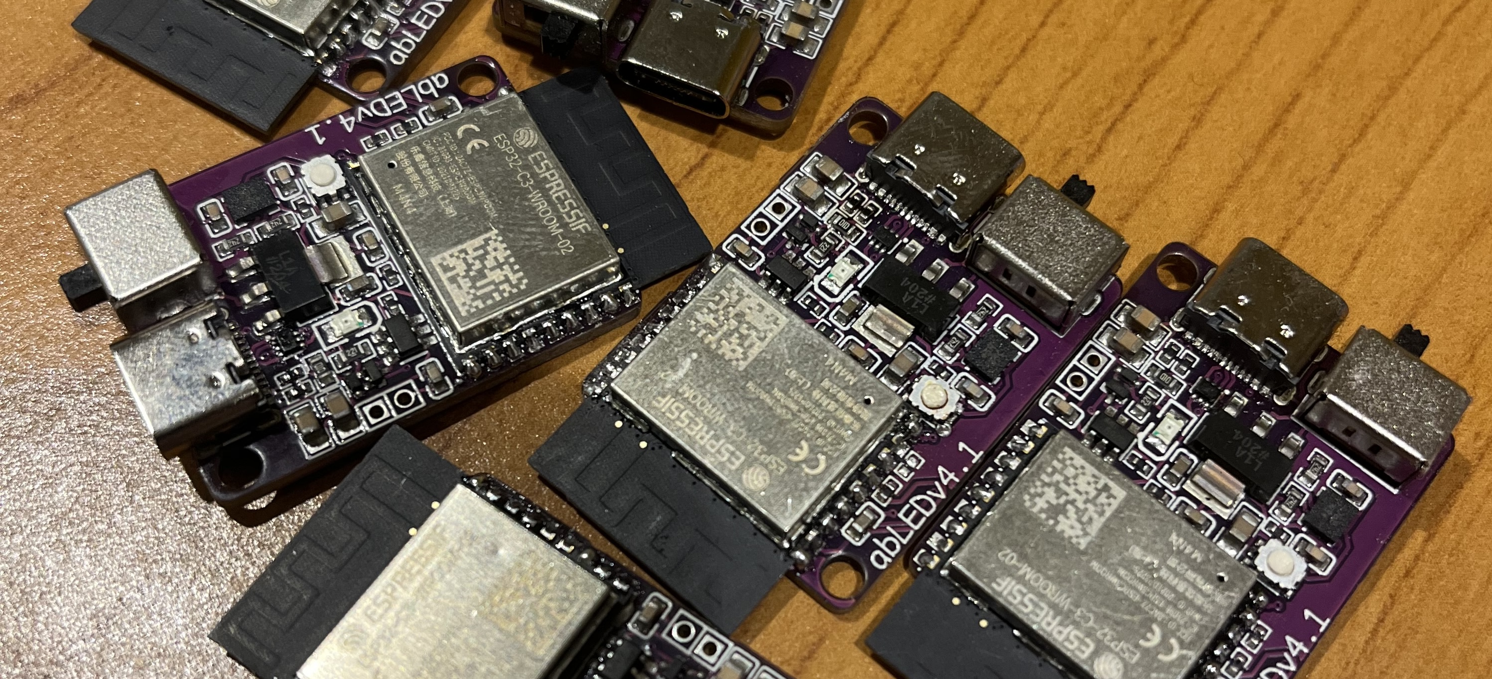
The immediately preceding version was v4.1 (shown above), which was operational and worked well! One feature I’m really proud of is the extremely sophisticated power path with switch that will completely disconnect the battery from all loads when in the off position, while still allowing the battery to be charged. When in the on position, plugging the device in puts all of the load on the power in and charges the battery, and will switch back to battery uninterupted when unplugged. While the power path worked great, the design had a few flaws that I felt needed to be improved before the huge time sink that is assembling a whole set of bands.
- The battery connected by a pair of 2mm pitch through holes, which lead to the soldered connection constantly breaking without strain relief (which I didn’t have the space to provide)
- Soldering the battery to THTs also meant they were not easily swappable
- I had just made a design refresh of the band which placed the PCB next to the battery instead of on top, meaning the design would now benefit from a smaller form factor
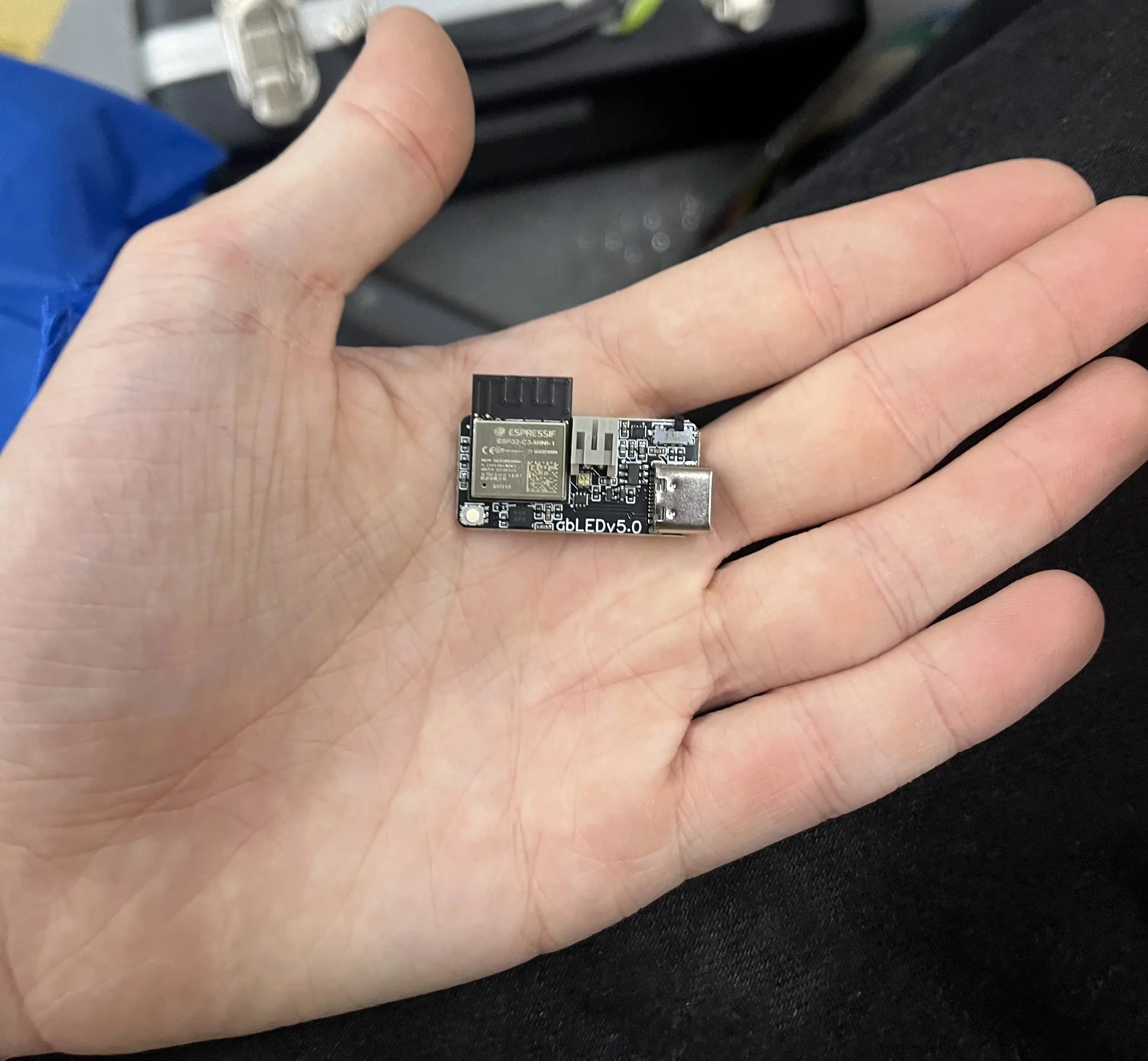
With v5, I lost many comforts of v4.1 – such as mounting holes and a hefty/satisfying slide switch. Also, I couldn’t assemble the boards myself since I switched from 0603 passives to 0402 passives – so I had to order them assembled. v5 had a more delicate switch that was at a worse angle, and a higher price tag, but the design shrunk from .95 inches wide to a mere .6 inches wide! Additionally, a battery connector meant that the battery was securely attached, and also easy to swap out.

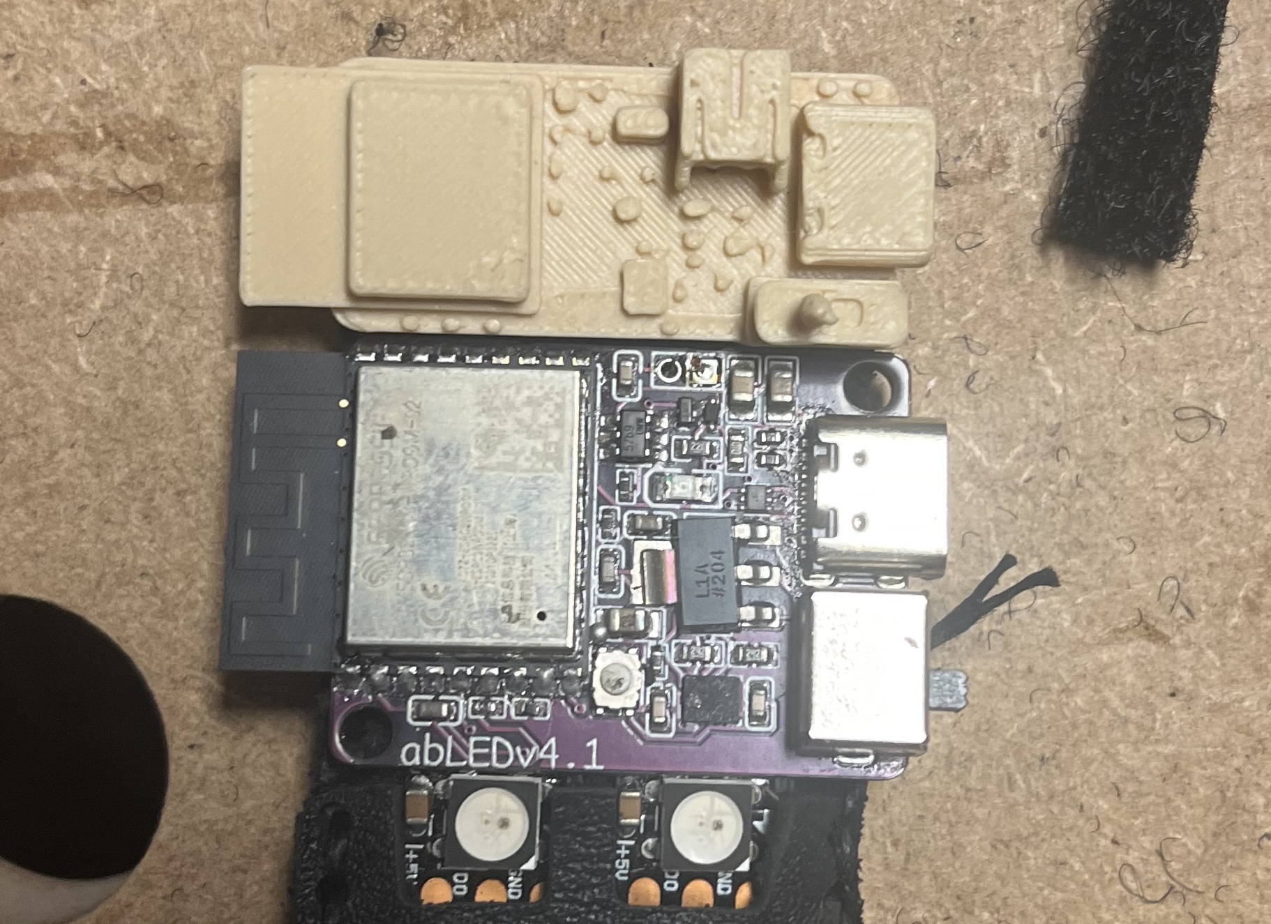
Early 3d printed mockup of v5
(which has the same dimensions as the final design)
next to v4.1.
Design
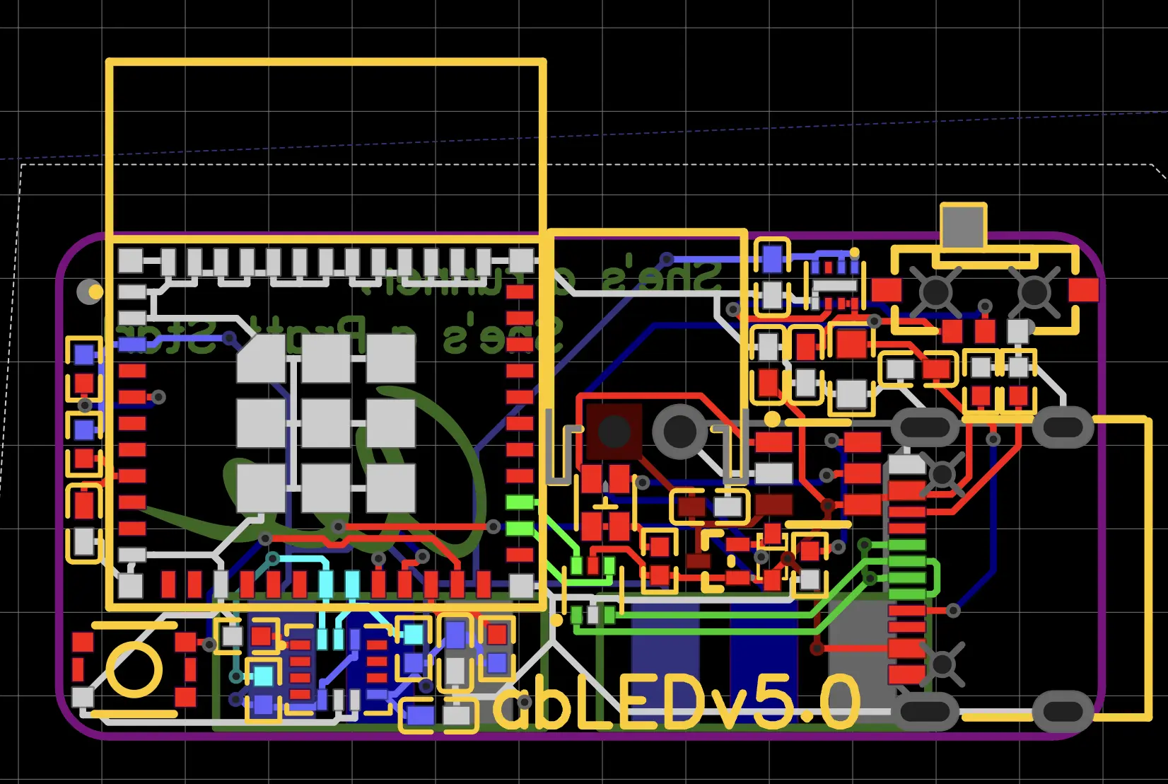
Put simply, this design was the same as v4.1 but with all components swapped for the smallest componenet of the same type that was still in spec. The LDO went from a classic AMS1117 (SOT-223 package) to the more foreign “NCP706AMX” LDO, which somehow manages >1A of current in a package measuring 1.2 x 1.6mm! Everything that could be 0402 became 0402, and the ESP32C3 module went from the standard WROOM module to the more compact (and more expensive) WROOM-MINI module. The routing was basically “move parts until the nets seem possible, route until you give up, decide to reduce design constraints, repeat” until I got it working. As always, these PCBs have solder pads on the bottom for soldering directly to LED strips.

Routing for v5
Aesthetics
These are black! Because they are visible on the outside of the bands. The back silkscreen says “She’s a runner, She’s a Pratt Star”, which I put on every one of my PCBs, referencing a Duke joke about the Pratt School Of Engineering.

Alright, yea. I got it pretty small.