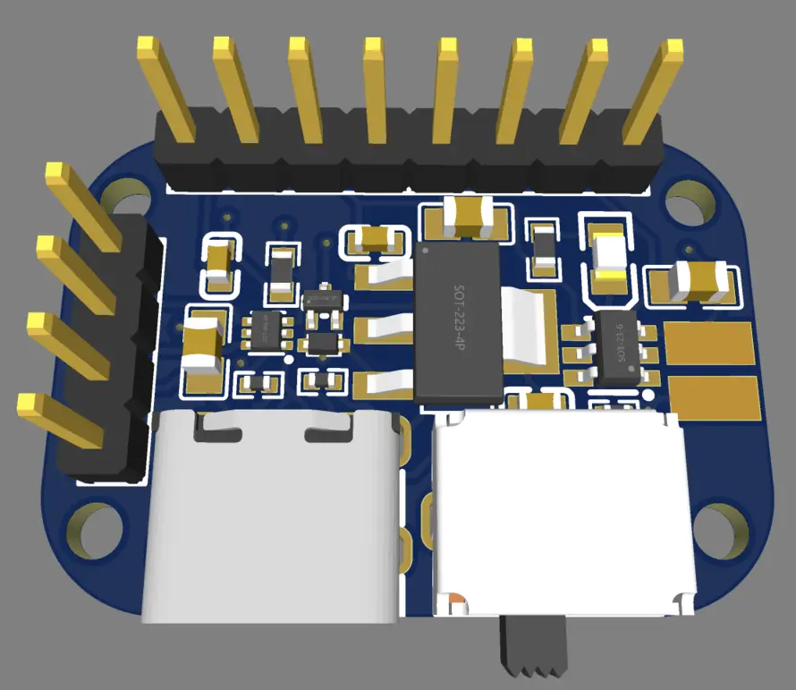
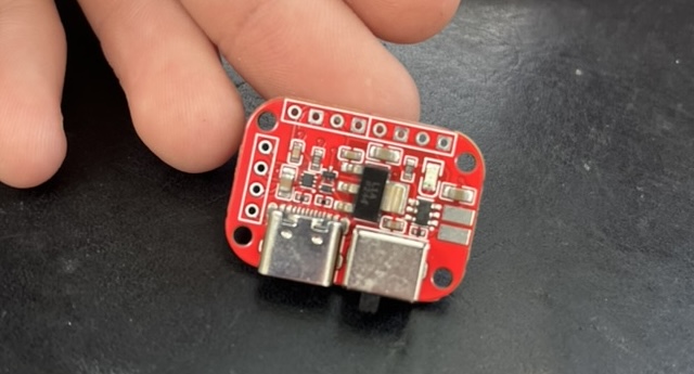
"Dream" Li-Po charger with Power Path
2024 Personal Project PCB Design
I was tired of cheap Li-po chargers that never had all of the features I actually needed, so I designed this one to have it all: Power path management! A physical On/Off switch! Mounting holes! And of course, USB-C.

Project Summary
This is a LiPo/Li-ion charger I designed to be more feature rich than the generic TP4056 chargers you can buy by the dozen on ebay (though admittedly it does use the TP4056).
Motivation
Most of what I build is battery-powered, and when I’m not making a custom PCB I want to have a nice charger module, but generic options are so often so barebone that they’re really frustrating to use. Some issues I wanted to adress were:
- Lack of Power Path. Cheap chargers don’t have a proper power path or an EN pin, so On/Off switches need to physically disconnect the battery, meaning the device can only be charged when switched on. This leads to me always forgetting to turn them off when I unplug them and then they die in my bag.
- Lack of mounting holes. I want to mount a charger, which has a USB port that will need to be accessed and handled, by something besides hot glue or press fit! Yet no common modules have mounting holes for screws.
- Connector Type. A lot of cheap modules still use micro-usb, which is disgusting. It is the age of USB-C!
- Protection. Not enough modules have protection chips for overdischarge or short circuit, and the TP4056 doesn’t have enough protection features by itself.
- USB lines. If I’m mounting this module as an external port, I don’t want a different port to get to my microcontroller (if I’m using one) but I still want access to it. I want this module to break out the unused D+/D- lines of the USB port.
- Outputs. It’s more convenient to have multiple outputs for V out and GND in case I have many disconnected subsystems so I don’t need a seperate place for those lines to come together.
Design
The design was pretty basic, I just tried to adress all the features I mentioned above in as small a footprint as possible. A lot of these features like power path and protection ICs I had made a schematic for already that I used in my ESP32 boards for my LED bands. Similar to those, the power path will completely disconnect the battery from all loads when switched off, while still allowing the battery to be charged. When switched on, plugging the device in puts all of the load on the power in and charges the battery, and will switch back to battery power uninterupted when unplugged. I decided to add a switch on the module, since I figured I’d be mounting the PCB in an accessible position anyway. I also added a 1.5A 3.3V LDO which can be optionally used for the outputs, since I often want 3.3V from a LiPo. If I’m boosting to 5V, I’ll have a seperate module to do that anyway. I don’t mind the inefficiency of an LDO compared to a switching regulator in this case as I’m nominally just dropping .4V.
Aesthetics
Not much Aesthetically here, except for a huge oversight: I forgot to put a silkscreen labeling the outputs. Now I have to look a the gerbers Every Single Time I wire one of these up. This was a one day project, and I must have gotten so wrapped up in finishing the design I completely forgot about the silkscreen. Embarrassing.
