Portable Nixie Tube Pomodoro Timer
2024 Class Project
This one has it all: ICs from the 70s! 200 Volts! Extremely Competent Perfboard Circuits! And of course, USB-C.
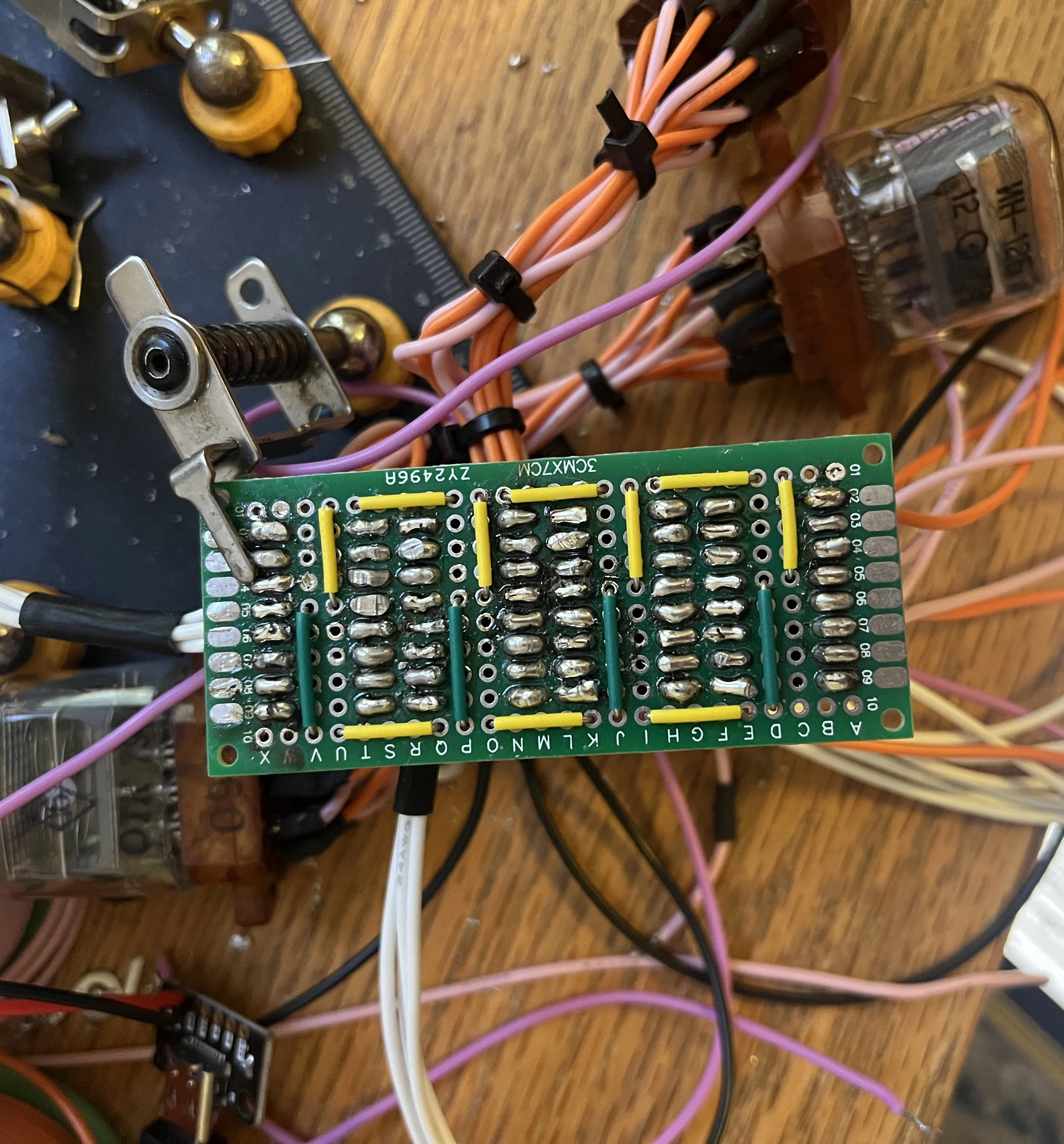
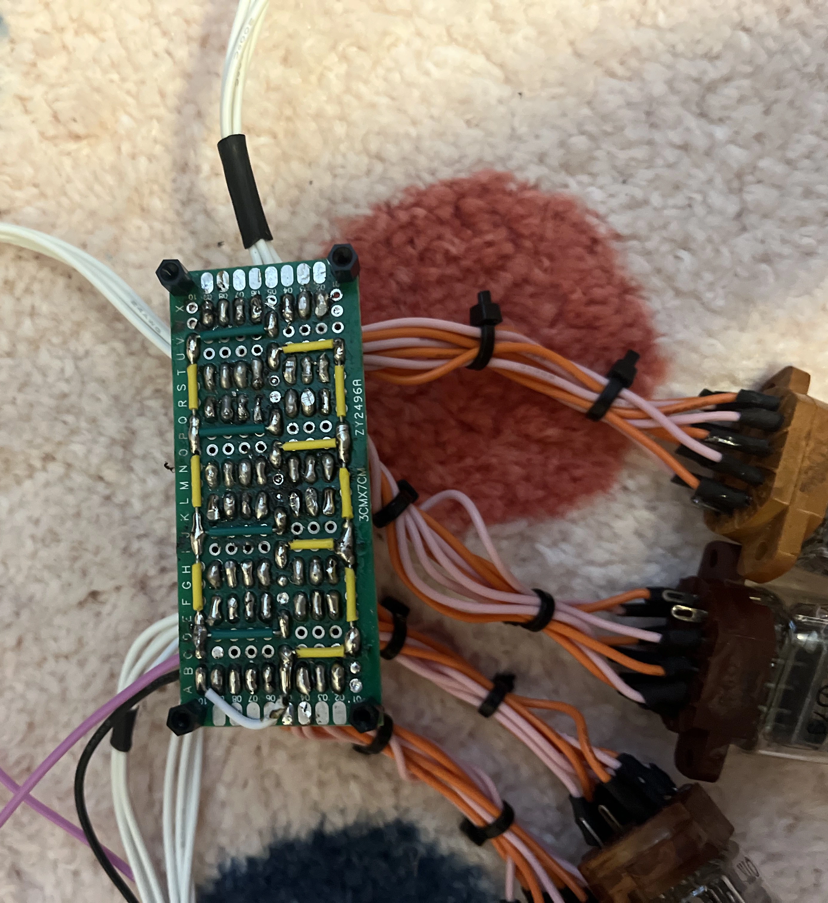
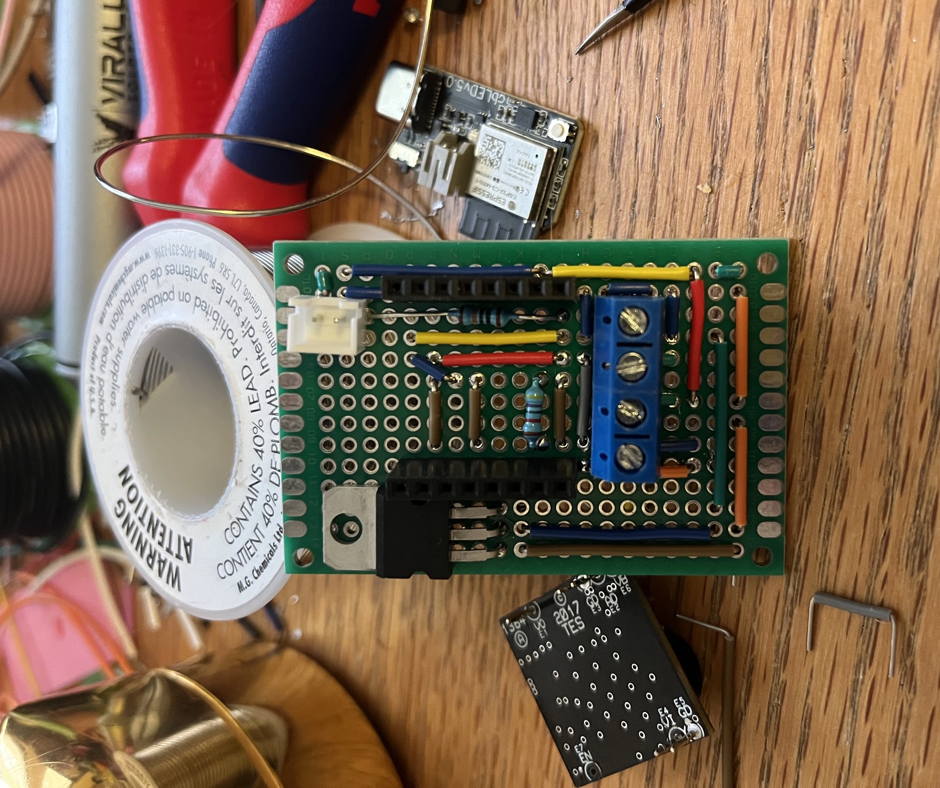
The main attraction of this one is probably the gorgeous perfboard circuits – which are my best ever – so I’ll show them off at the top.

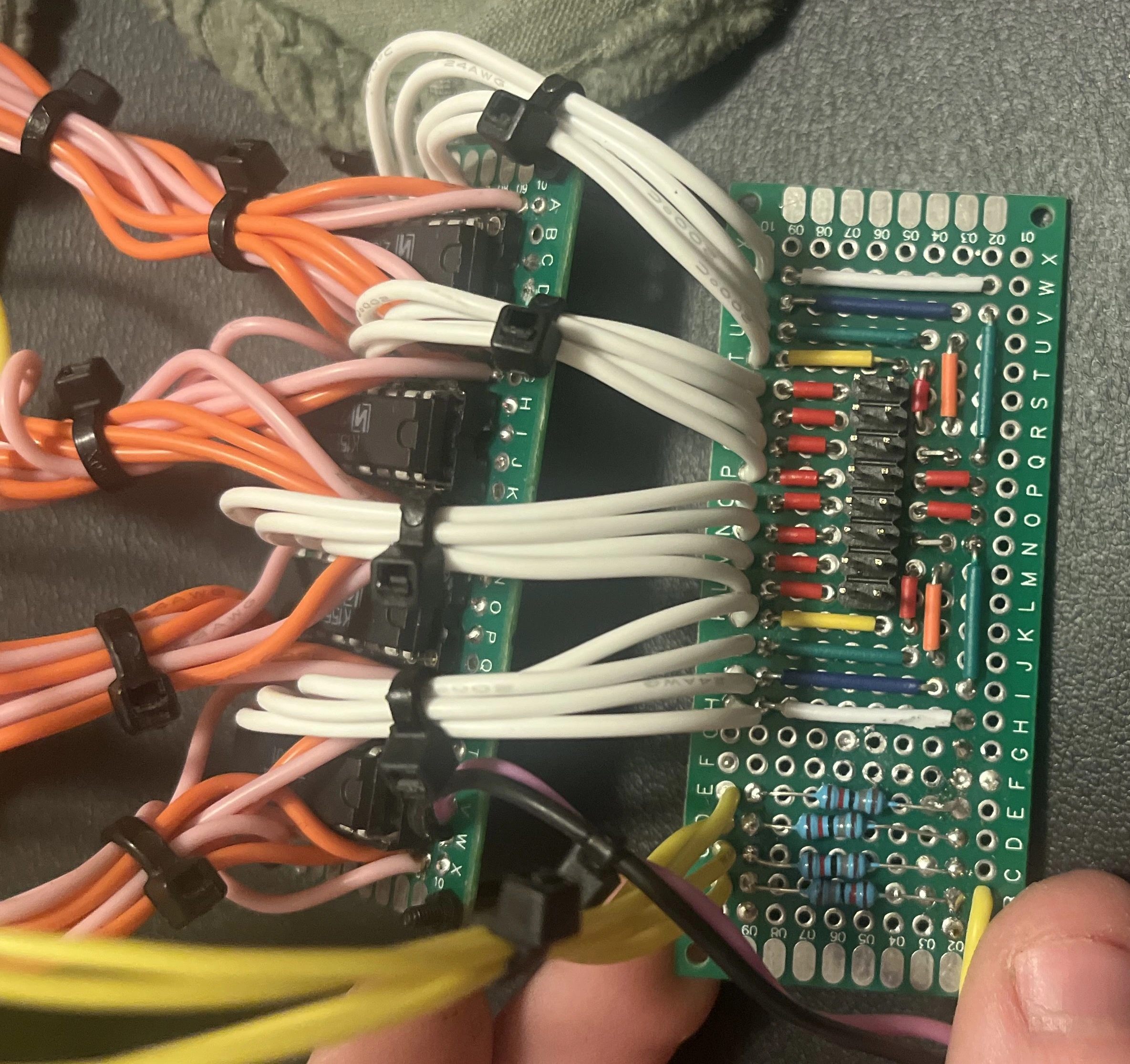
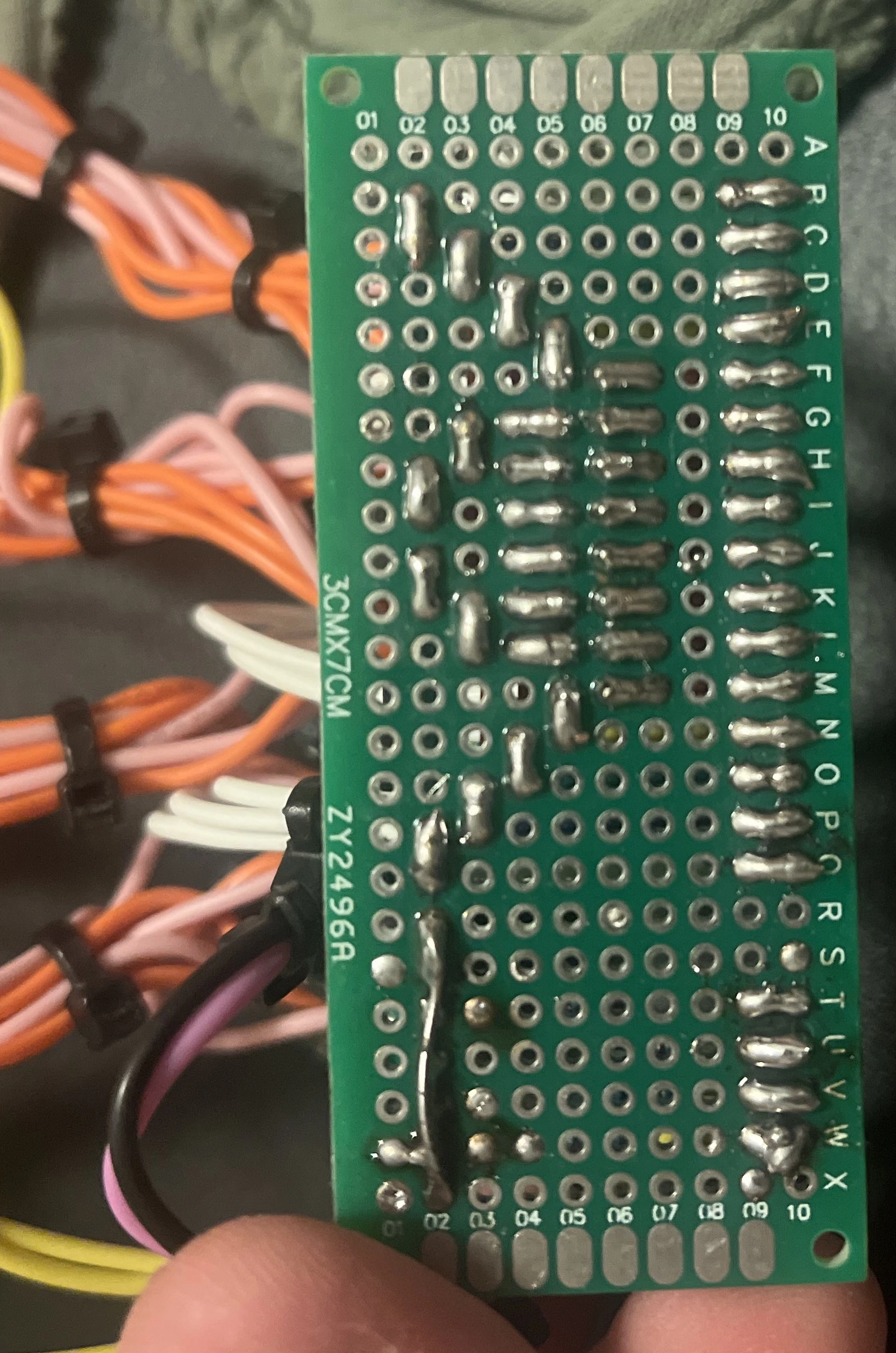
Project Summary
The original idea for this project was a pomodoro timer (a countdown timer that alternates intervals for use as a work/break study technique) that used vintage nixie tubes as a display. I had hoped to exclusively use “retro” parts that were being manufactured in the ’70s.
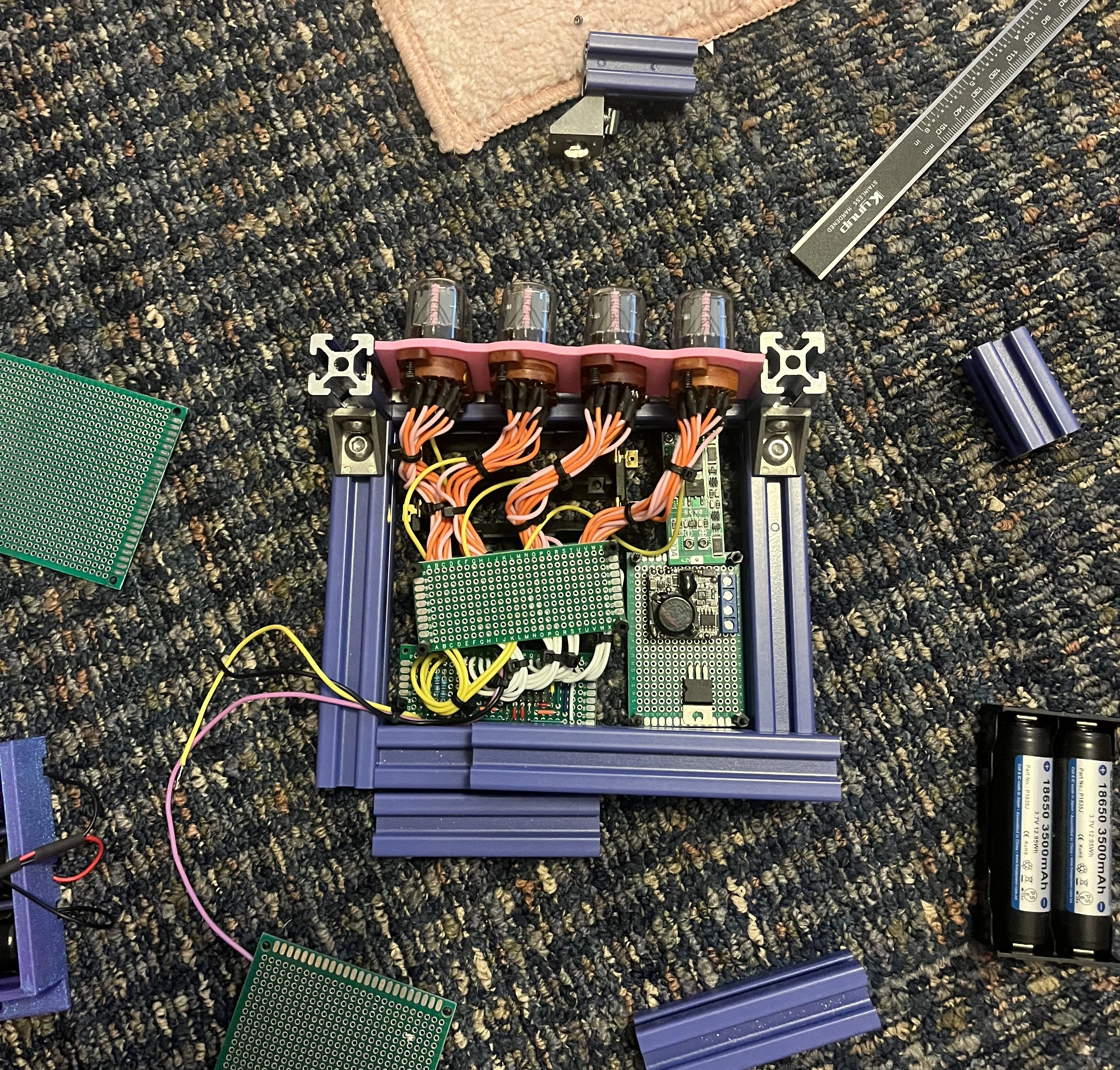
An in progress look at the clock.
Motivation
I had just taken a digital systems class, and wanted to embark on a project that used my new skills. I had also been to an amzing electronics shop while studying abroad in london (Cricklewood Electronics!) which had thousands of ICs and components that had been collected over many decades, and that inspired the “retro” aspects of this build. My main goals were:
- For the project to only use digital logic. This meant no microcontroller, nothing that could think: Butlerian Jihad rules.
- To have a “retro” vibe, I wanted handmade circuits with THT components and DIP packages. I set the (arbitrary) rule that I couldn’t use ICs made after the date of my nixie tube decoder ICs, which were mid-70s. This was to avoid having a board that maybe looked “retro” but just had some microcontrollers in DIP packages, or other ICs that made my job “too easy”.
- Extremely accurate timekeeping. This was just because I’m a bit of a snob and didn’t want to use a 555 timer because it could swing as much as a few minutes if I used the device for a couple hours.
- A reasonably compact enclosure so I would actually take it to the library.
- The ability to select intervals of work/study, the two most popular being 25/5 and 50/10.
I chose to stretch the ’70s rule to not include power components, as I wanted modern high-density Li-Ion batteries and USB-C charging. I also wanted to maximize safety and considering the tubes required 200V, I chose to use a modern boost converter instead of hacking together a flyback.
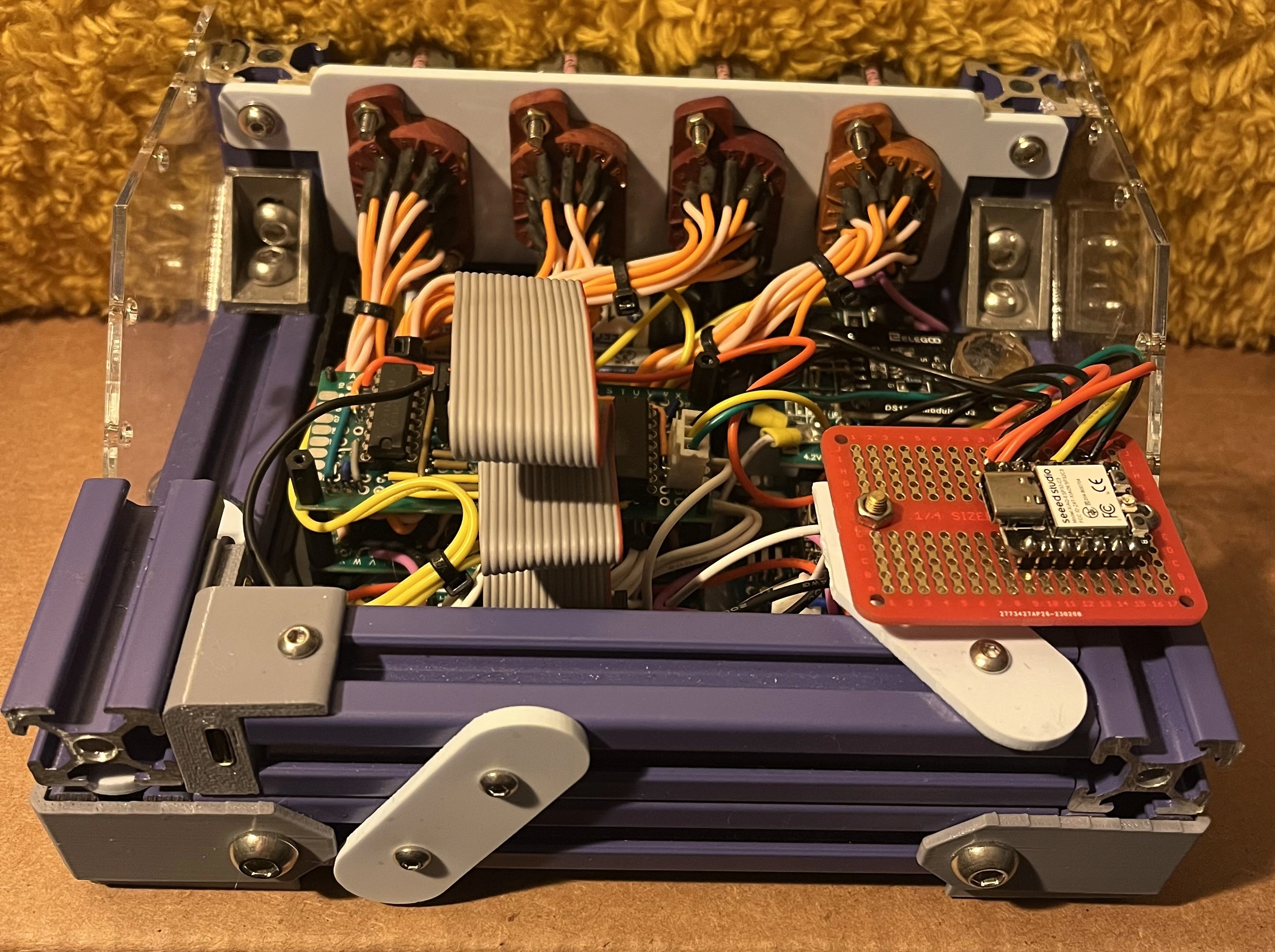
Ultimately, I ran out of time for this project as the semester got more intense, and so I didn’t accomplish all these goals. The clock itself is functional, but just so; I ended up slapping a microcontroller and i2c RTC on it just to have something that worked. It still has 3d printed parts which I don’t think fit the retro aesthetic at all, and the enclosure isn’t even done being built (it lacks a top plate). There’s a lot I’d love to finish, fix, and optimize on this one when I come back to it!
Design
The design was heavily influenced by the size and depth of the nixie tubes, which I mounted in equally retro sockets that were also very deep. I wanted to avoid 3D printed parts as much as possible, so construction came down to either modifying a chunky abs enclosure or building something with aluminum extrusion. I had this nice blue extrusion lying around, and went with that. The paneling is done with lazer cut acrylic.
Layout/Mounting
A huge point of pride for this project is how easily the whole thing can be taken apart. With just a screwdriver, every perfboard can be removed from the device and all connections between boards can be disconnected as well. Why? Because the road to integration hell is paved with hot glue and soldered inter-board connections. Each perfboard circuit is monted to a bottom plate along with the battery housing, and the whole plate is screwed into the underside of the aluminum frame. Ring terminals, screw terminals, JST connectors, and ribbon cables are used to hook the boards up to each other.
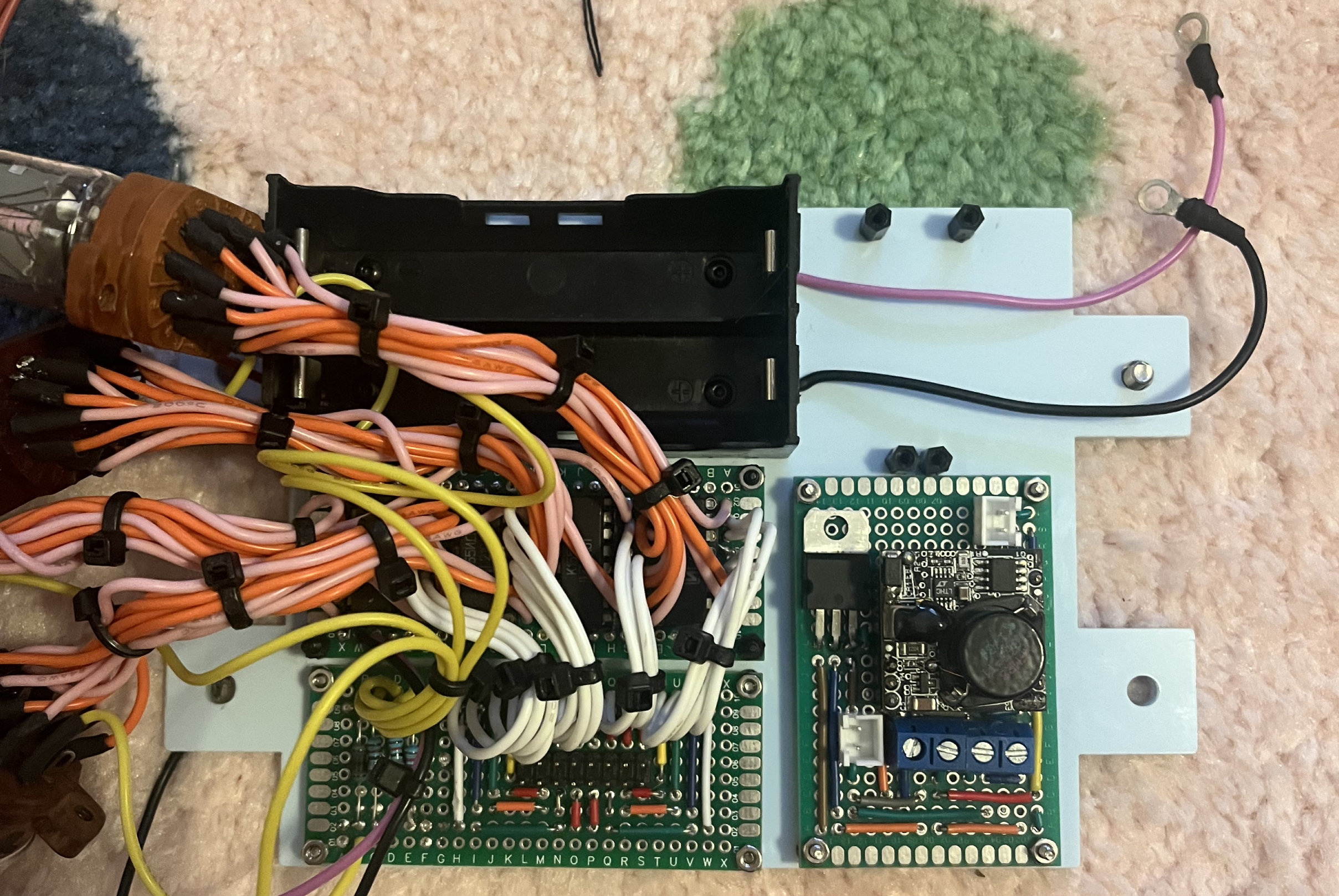
The bottom plate, with some of the perfboard mounted.
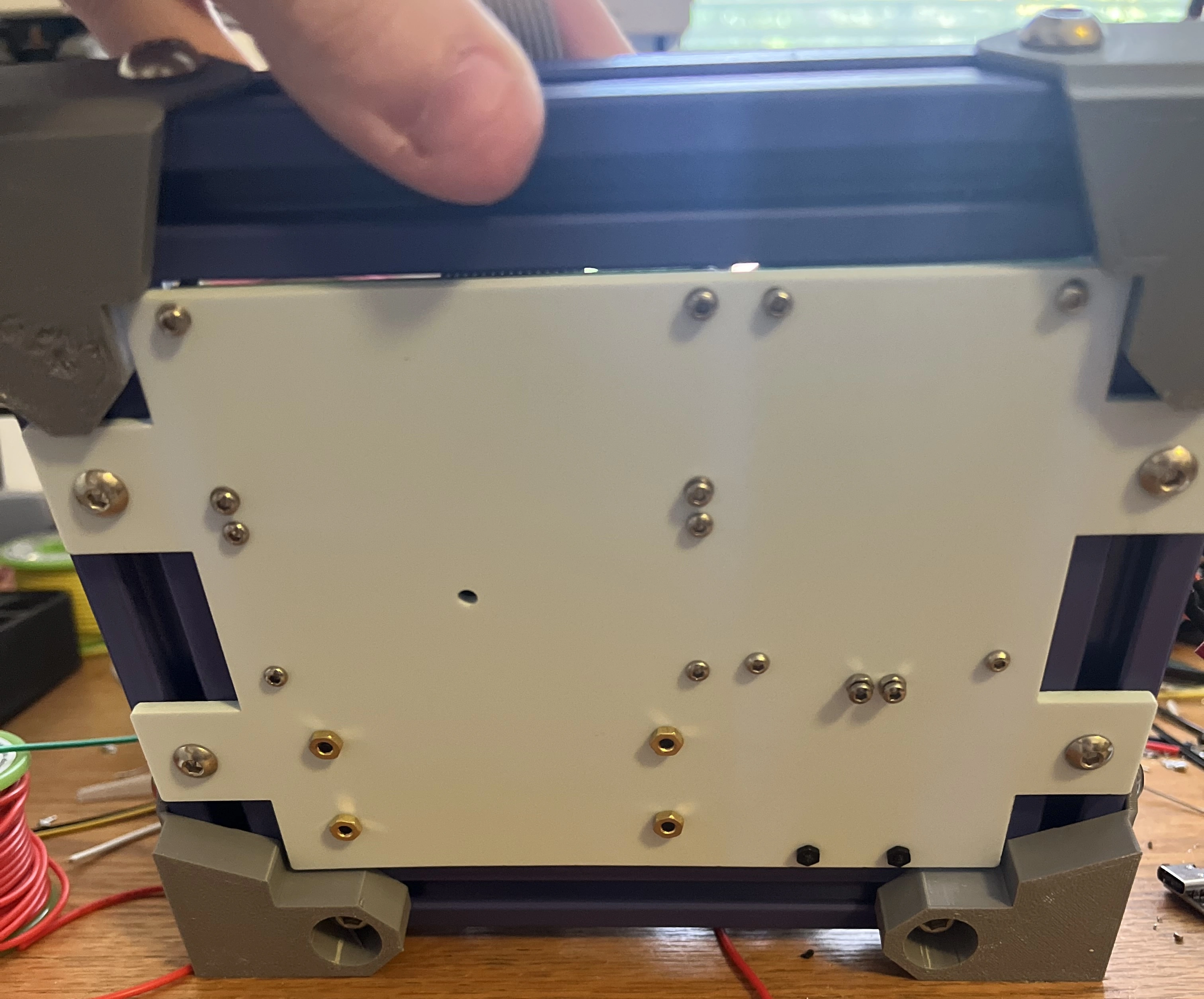
The underside of the clock.
System Design
The clock starts with the nixie tubes, which take around 200VDC and have 1 input per digit, common anode. The 48 wires from my 4 tube sockets go to a perfobard that connects each tube to a vintage nixie decoder IC. The 4 ICs each take a 4 bit parallel input to indicate which digit the tube should display, and those 16 connections go to a seperate perfboard which reroutes them into a more logical order and into a connector for a 16 wire ribbon cable.
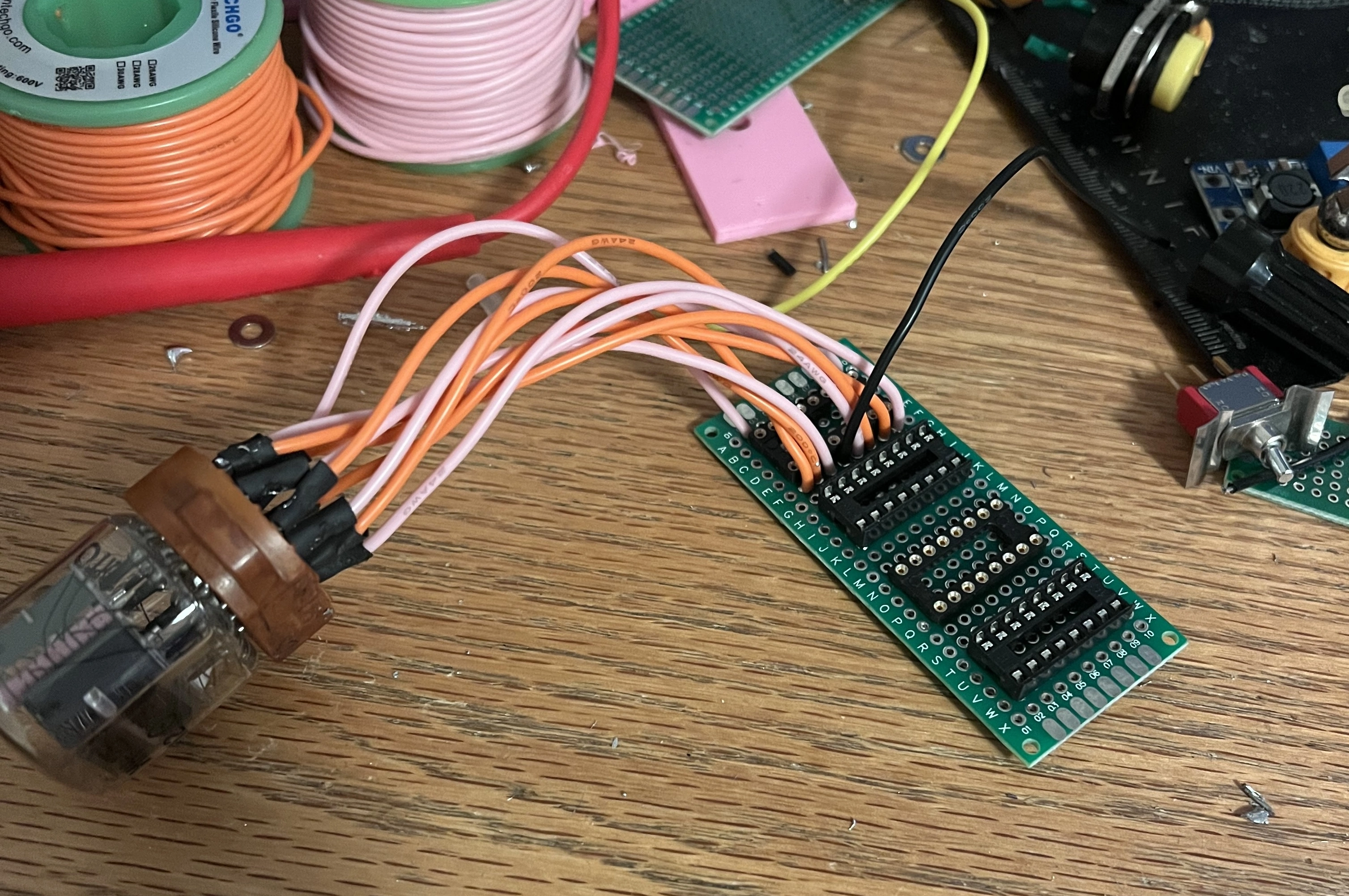


Clockwise:
One tube wired to the driver IC board.
The underside of that board and the pretty connections.
The extension to the drivers, for adapting to a ribbon cable.
The board also has power inputs, which are supplied by the power board. Power is supplied by two 18650s in parallel through a BMS, which gives a nominal 7.4V that is used to power most of the ICs and the boost converter. The power circuitry perfboard holds a boost module for stepping up the voltage to 200V nixie levels as well as things like ports for an on/off switch and a linear buck regulator that drops the 7.4V to 5V for some of the ICs, such as those used in timekeeping.

The power board.
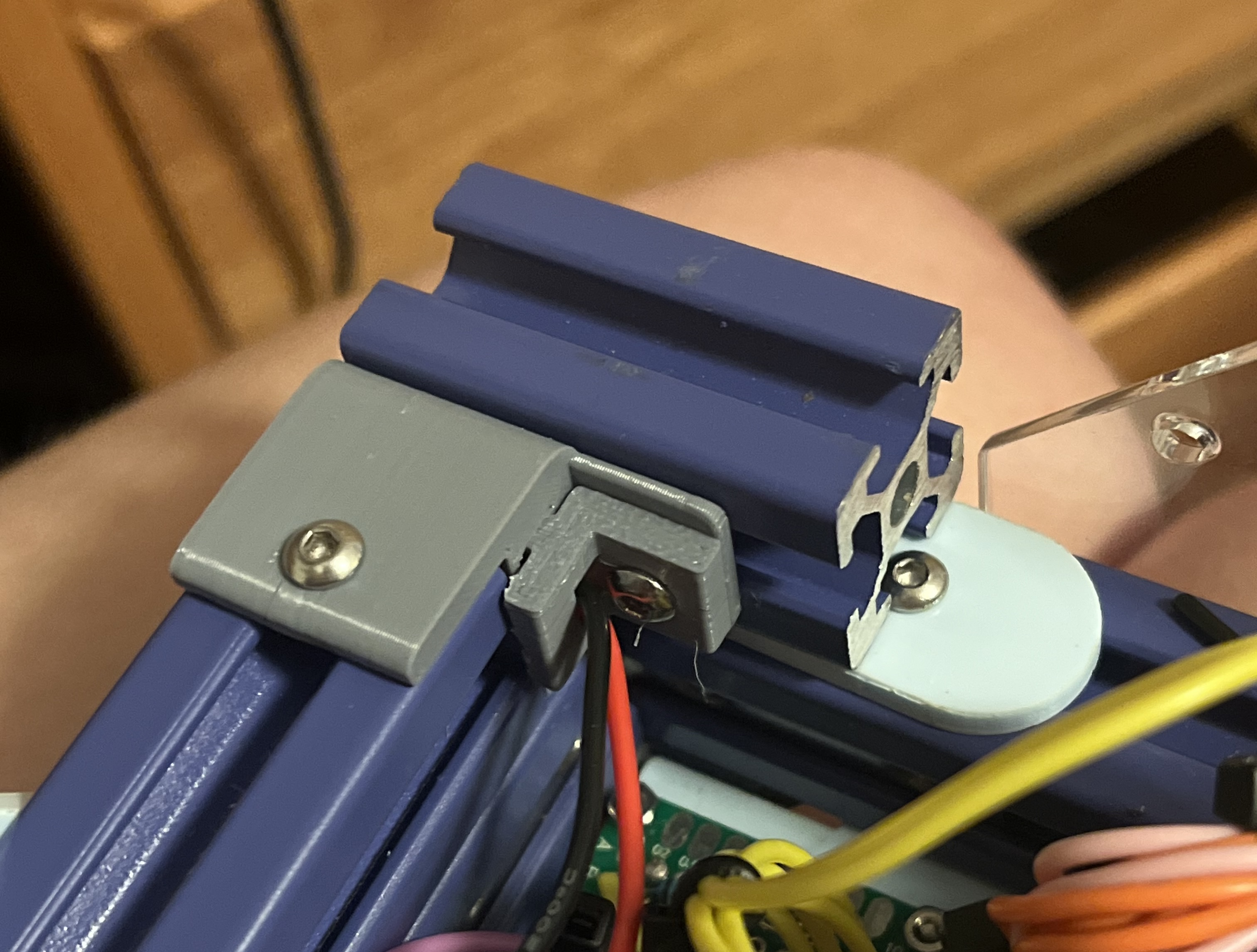
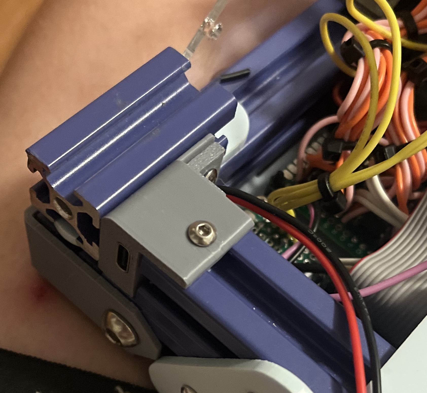
For charging, a USB-C PD chip requests 9V over USB-C which goes directly to the BMS, and the chip has a small 3d-printed mount that attaches to the extrusions on the rear.
Cut for Time
While making this project, I made significant progress on many of the goals listed in the Motivation section. I made an extremely accurate timekeeping circuit using a CD4060 IC, a flip flop, a watch crystal, and a few passives that kept time within 2 seconds over the course of 8 hours. I also designed and simulated a state machine that could count down work/study intervals and toggle between 25/5 and 50/10 interval sizes. I got so far as constructing this system on a breadboard using some counters, flip-flops, logic gates, and muxes and even had the system working on bread-board! Unfortunately, my original power supply died around this time and in order to have a finished project by the deadline I decided not to adapt this ciruit onto perfboard, instead spending my time remaking the power system with completely different parts.
Quick Fixes
To solve the problem of where the ribbon cable connects now that there’s no counting system, I made a quick little adapter that hooks up the 16 inputs to the outputs of two shift registers, and wired those shift registers to a microcontroller.

All that was left to do was slap everything together, haphazardly bolt on a microcontroller, and run out of time to manufacture the top acrylic panel.
Future Plans
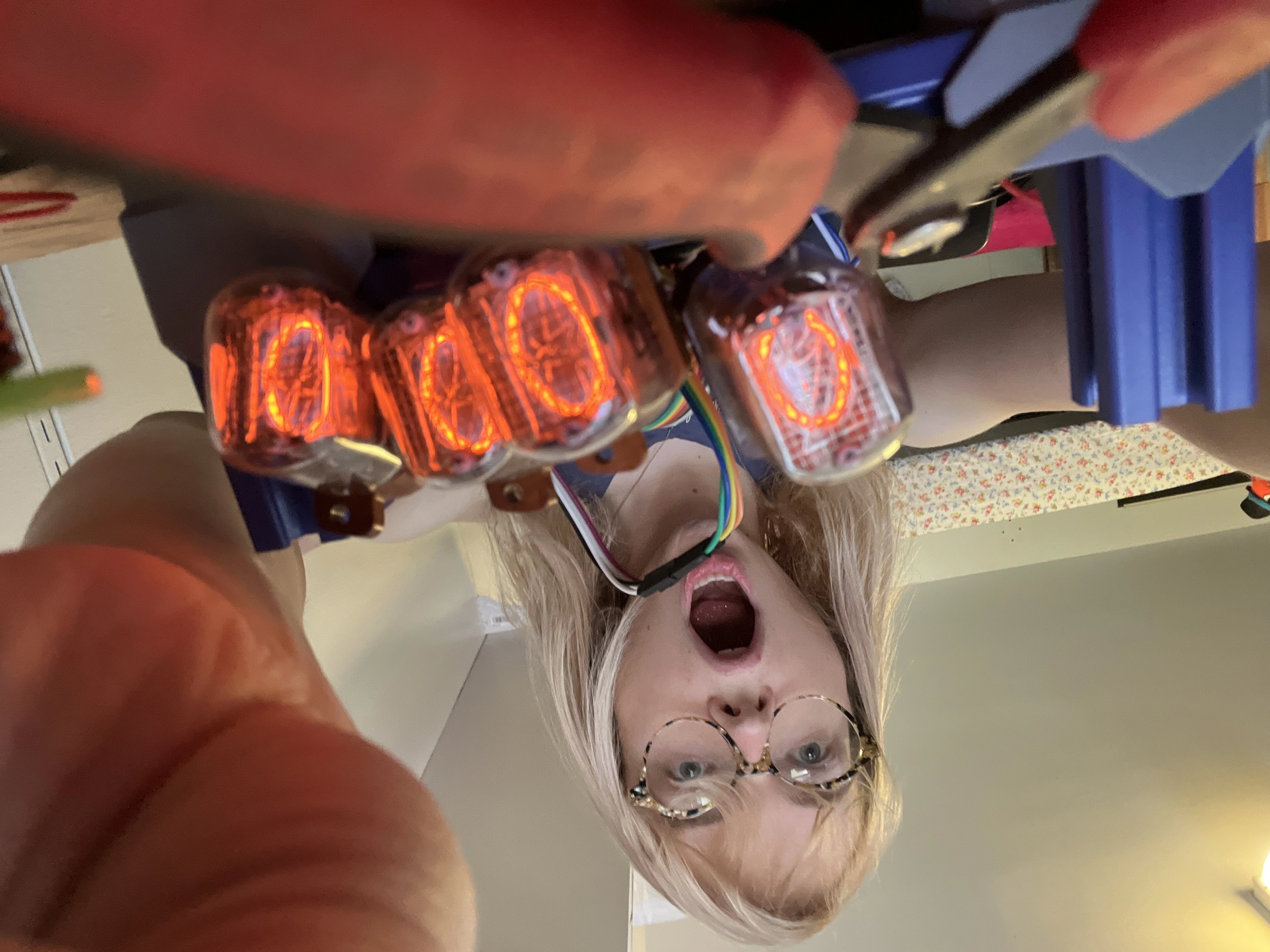
This is a build I really want to go back to and polish up. I’d love to remove that eyesore MCU and implement my counting circuit, and to freshen up the exterior. I wish I’d taken more photos before the build got packed into a “revisit when available” box – for instance, the only photo I have of the tubes actually functioning is this one of me looking like a very excited doofus.
